A valvein a 500 rack.
A double-wide 500-series colour box. It takes a line-level signal, lets you choose how hard to push a transformer, an EF86 valve and a pair of clipping diodes, then blends the result with the clean signal.
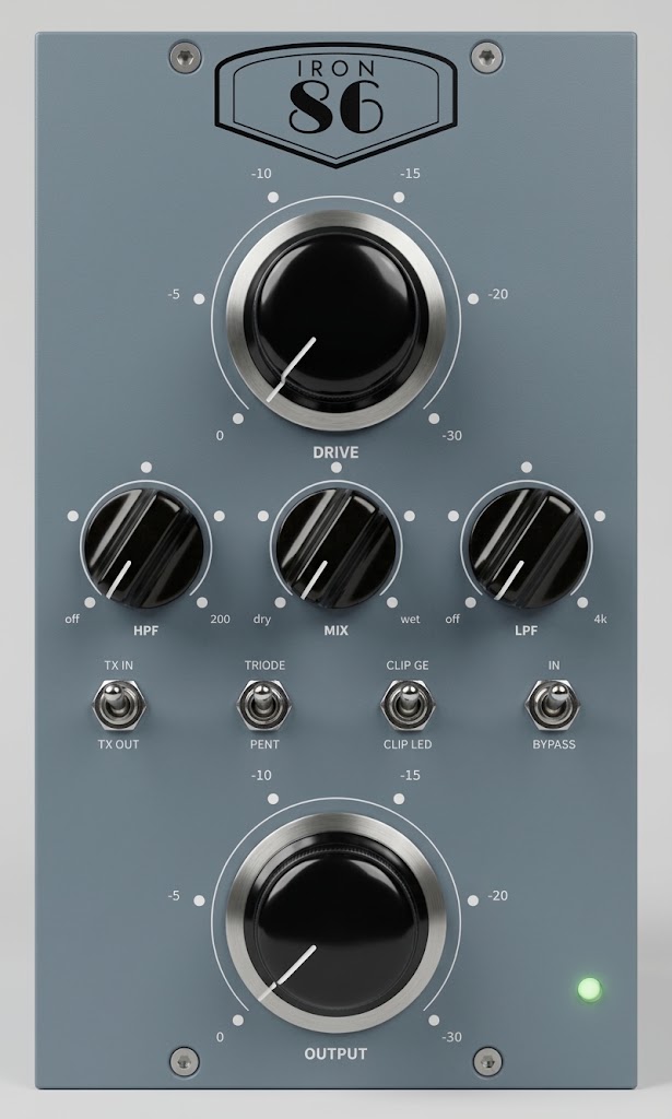
Three places to saturate, each with a switch.
Every block exists to give you separate control of where the saturation happens. The high-pass sits before the valve and the low-pass after the clipper, and neither touches the clean signal that MIX blends back in.
Transformer, or not
IRON sends the input through a transformer. CLEAN swaps it for an electronically balanced receiver, for tighter lows and a more open top. The two are level-matched.
INA134 receiver
EF86, pentode or triode
DRIVE sets how hard the grid is hit. Triode is smoother and mostly second harmonic. Pentode is edgier, with second and third about equal when pushed.
12-step DRIVE ladder
Germanium or LED
A germanium pair clips soft and early, from about +4 dBu. A red LED pair clips harder and later, from about +10 dBu. Makeup gain keeps both at the same level below clipping.
Red LED pair
Bridge driver into iron
MIX crossfades the clean and saturated paths, kept in phase. A balanced driver feeds the output transformer, wired 1:1.73, then a stepped OUTPUT attenuator.
Hairball EA-1166-500
Write a setting down and get it back.
DRIVE and OUTPUT are 12-position switches with hand-built resistor ladders. DRIVE has two decks: one pushes the valve, the other pulls the saturated path back by the same amount, so it changes saturation and leaves volume alone.
- DRIVE0 to −30 dB, 12 steps
How hard the valve is driven. With +4 dBu in, the grid sees +16 dBu at 0 and −14 dBu at −30.
- HPFOff to 200 Hz, 12 dB/oct
High-pass before the valve, on the saturated path only. Keep the bass out of the saturation and let MIX bring it back clean.
- MIXDry to wet
Crossfades the clean signal, taken after the input stage, with the saturated path.
- LPFOff to 3.6 kHz, 12 dB/oct
Low-pass after the clipper, on the saturated path only. Tames the fizz.
- IRON / CLEANToggle
Input transformer in, or an electronically balanced input in its place.
- TRIODE / PENTToggle
Changes how the valve's screen grid is connected. Only its AC return moves, so the switch doesn't pop.
- CLIP GE / CLIP LEDToggle
Germanium or LED clipping diodes. The clipper is always in circuit.
- IN / BYPASSToggle, green LED
Relay hard bypass. An unpowered module passes its input straight to its output.
- OUTPUT0 to −30 dB, 12 steps
A balanced attenuator after the output transformer. About +10 dB of gain at 0, and unity near −10.
- Input
- Valve
- Clipper
- Drive
- Module
This drawing follows the current panel art. The render at the top of the page is an earlier finish study, so its scales and legends differ.
224 volts from a rack that offers 16.
A 500-series slot gives a module ±16 V and 130 mA per rail. Two small switching supplies on the main card turn that into everything a valve needs. Both run across the two rails together, which halves the current taken from each.
High voltage
LT3757A boost, 300 kHzBoosts the 32 V between the rails and filters it twice, for about 224 V at the valve. It has a current limit, a soft start of about 0.6 s and a resettable fuse. A bleeder brings the voltage under 50 V about 11 s after power-off, and a red LED on the board stays lit while it's present.
Heater
ZXLD1362 constant-current buckRuns the heater on DC at 6.3 V and 200 mA, trimmed with a 25-turn pot. Because the supply sets the current, a cold heater can never surge. The valve itself runs at about 12 % of its rated plate dissipation.
| Rail current, simulated | +16 V | −16 V | 500-series limit |
|---|---|---|---|
| Running, bypassed | ≈ 100 mA | ≈ 100 mA | 130 mA |
| Engaged | ≈ 109 mA | ≈ 100 mA | 130 mA |
| Worst case, full output at 40 Hz | ≈ 120 mA | ≈ 110 mA | 130 mA |
One part measured. The rest simulated.
The prototype isn't built yet, so almost every figure here comes from simulation. The exception is the output transformer, which has been measured on the bench. Measurements replace the rest as they come in.
| Parameter | Condition | Simulated | Bench |
|---|---|---|---|
| Overall gain | OUTPUT at 0 | ≈ +10 dB | Pending |
| Valve stage gain | Pentode / triode | 26.7 / 22.4 dB | Pending |
| Saturated-path THD | 1 kHz, +4 dBu in, DRIVE −30, pentode / triode | 0.26 / 0.16 % | Pending |
| Saturated-path THD | DRIVE −12, germanium, pentode / triode | 3.1 / 2.0 % | Pending |
| Saturated-path THD | DRIVE 0, germanium, pentode / triode | 30.7 / 21.9 % | Pending |
| Level match | Germanium against LED, below clipping | Within 0.06 dB | Pending |
| Level match | IRON against CLEAN, triode against pentode | Within 0.1 dB | Pending |
| High-pass range | Saturated path, 12 dB/oct | 10.6 to 200 Hz | Pending |
| Low-pass range | Saturated path, 12 dB/oct | 58 to 3.6 kHz | Pending |
| Valve supply | Valve fitted, 2 mA | 224 V | Pending |
| Power-up delay | Bypass relay holds off while the valve warms | ≈ 10 s | Pending |
| Output transformer inductance | Primary, 40 to 100 Hz at about 1 V | — | 1.04–1.17 H Measured |
| Panel | 500-series double-wide, aluminium | 75.7 × 133.4 mm | |
The valve model is fitted to one datasheet point and the transformer parasitics are estimates, so treat the distortion figures as a guide until the bench numbers arrive.
Made to be left switched on.
The valve lies flat inside the module on the main card, beside the two transformers. All parts sit on one side, facing the empty second slot.
- BypassA relay, fail-safe when unpowered. At power-up it waits about 10 seconds, so the valve's warm-up thump never reaches the output.
- LEDWired in series with the relay coil. It lights when the module is in circuit, and only then.
- DiodesThe germanium pair is new old stock and sits in sockets.
- BoardsA four-layer main card with gold edge fingers, and a control board behind the panel.
- PanelLaser-cut 2.3 mm aluminium, slotted to fit both common rack hole heights.
Rev A, ready to build.
The Iron 86 design is signed off and the valve and transformers are on the bench. Leave your email and we'll send measurements, sound clips and the price once the prototype is running.